


The Windbelt is a very simple design that can be self modified and enhanced to suit the needs of the user. The main components are a containing bracket, two copper coils, two strong button magnets, a ribbon and some bolts and nuts to piece together the entire system.
• Bracket
The bracket holds together the entire unit. It can be fabricated from any available material such as treated timber, aluminum or plastic. The bracket requires a top and bottom piece and four spacer pieces. (See drawings for dimensions). It is important to consider the lifespan of the material since exposure to the elements is imminent. Weather treatment and protection will need to be applied, or else the Windbelt can be sheltered in an environment that channels wind through the capture zone.
• Copper Coils
The copper coils provide the medium for electromagnetic induction, as explained in the concepts section. According to Faraday’s law of induction, the induced Electromotive Force (EMF) is directly influenced by ‘N’, the number of turns in a coil. We plan to use coils that have the maximum number of turns to fit in the available space between the bracket and the ribbon. To reduce the cost of the unit, we hope to make use of available electronic waste. There are copper coils in almost all appliances such as televisions and speakers. Any of these coils will potentially work in the Windbelt.
• The Ribbon
The ribbon is the platform for the entire functionality of the Windbelt. When exposed to wind above 4m/s the ribbon in our Windbelt will experience aeroelastic flutter. Wind will cause the ribbon to move up and down with high frequency oscillating motion. It can be pictured to be similar to the flutter of a tarp on the back of a ute, or the vibration of a piece of grass stretched between your fingers. The material for the ribbon can be anything durable enough to withstand monsoon weather and high wind forces. It is key for the ribbon to be as light as possible so that the cut in wind speed for flutter is minimised. The ribbon also needs to be torsionally strong so that the oscillation is as linear as possible, with little twist during the motion.
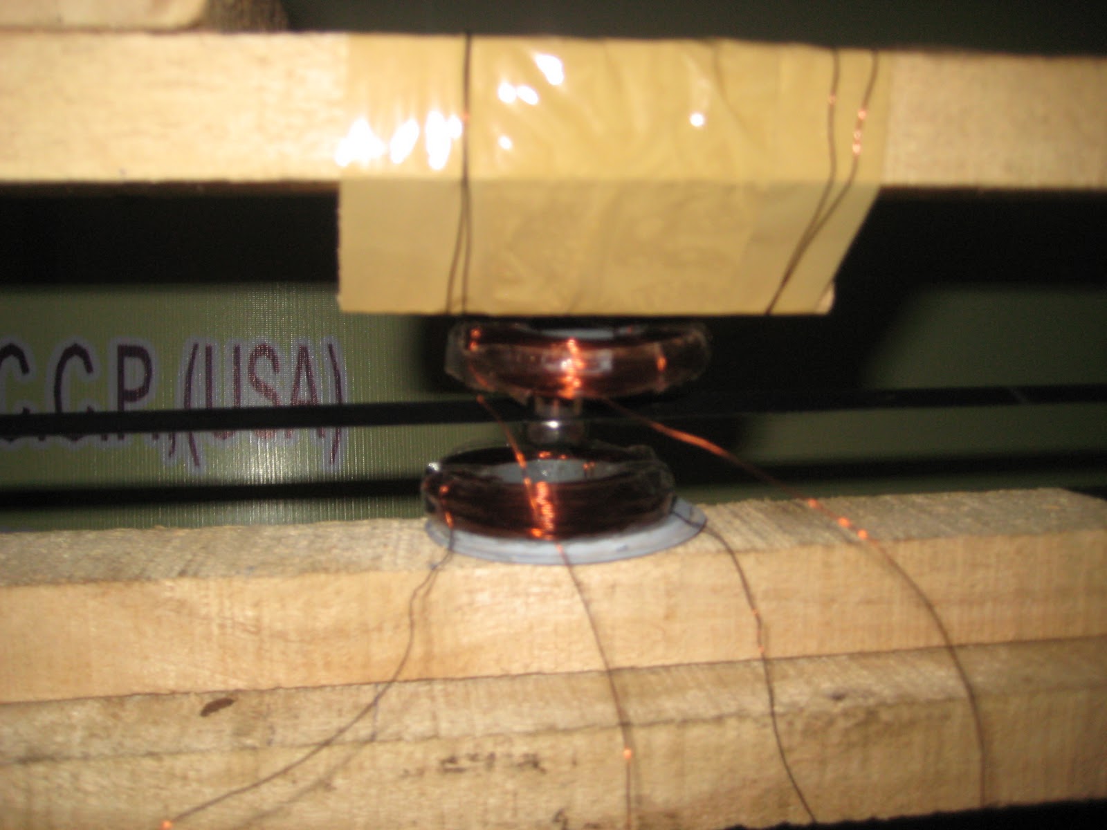
• Magnets
Two button magnets are attached to the ribbon in line with the centre of the copper coils. Joining the magnets on either side of the ribbon means they naturally attract, and using strong magnets will prevent movement over time. The stronger the magnetic field, the greater the magnetic flux and thus the larger induced current. As the magnets move up and down with the flutter of the ribbon the polarity of the field through the copper coils reverses. This change in polarity results in an alternating current best represented by the sine wave in figure. To capture the power output from the Windbelt, we plan to connect the wires from the copper coil into a rectifier for AC to DC conversion, and then plug the DC power into a appropriate applicant.
CONSTRUCTION• Timber was measured, marked and cut to length into four pieces using an electrical circular saw- 2 X (Top and Bottom frame pieces)- 4 X (Spacers)• All pieces of the frame were aligned.• Insulated copper wire was hand-wound around a hollow plastic tube as evenly as possible for about 100 turns to make a copper coil.• Once the first coil was wound, a section of straight wire approx 300mm long was left unwound to allow the circuit to reach from the top to the bottom of the frame. The second coil was wound at this point, and after 100 turns, some excess wire was left free. This would allow an appliance, rectifier, or, in the case of our prototype, a multimeter to be introduced into the circuit.• Ribbon was then tightly clamped in one end of the frame by tightening.• To find the right tension in the belt, a fan was used to provide a constant stream of air while the belt was pulled tighter. When the belt fluttered with the most effective amplitude and frequency then it’s fixed.• We tested a number of materials for the belt ranging from simple fabric ribbon, to videotape.• Insulation tape was the chosen medium as it had the least torsional rotation.• A two-part epoxy was mixed to create a strong adhesive, and the copper coils were glued to the frame and left overnight to set.• We now have our completed Windbelt power generator.
Any idea where one can get copper wire? But more importantly, where can someone get the converter?
ReplyDeleteYou say: "connect the wires from the copper coil into a rectifier for AC to DC conversion, and then plug the DC power into a appropriate applicant."
Where can I get these two pieces?
Thanks,
what kind of ribbon should i use ?
ReplyDeleteYou made some respectable factors there. I regarded on the web for the difficulty and found most people will associate with with your website. betfair online casino
ReplyDeleteI would recommend you to add a video as well. It will make it much easier for us to follow your DIY tutorial. Thank you
ReplyDelete